 Howe’s discovery of the expansion link with which to join the forward and back eccentric rods of a typical gab gear removed all the awkwardness in use and provided a continuous control from full forward to full back gears and all expansions in between. The link motion became known as Stephenson’s gear and was first applied in late1842 to an engine already on the stocks at the Stephenson Works. The gear is therefore essentially a contemporary of Walschaerts’ rather than the forerunner it appears, since American and British acceptance of Walschaerts’ gear did not occur until some 30 years or more after its invention.
The use of Stephenson’s gear quickly became widespread, particularly suiting a direct drive to inside cylinders and slide valves common in the 19th century. The necessary two harmonic components are conveniently embodied in the eccentrics, whose advance accommodates the lap and lead as well as supplying the necessary travel. The gear can be properly designed to deliver incomparable steam distribution, highly dependent upon critical suspension. The general lack of understanding this latter gave rise to widespread use of end suspension of the gear, something which should never have been perpetrated, as the results are so poor.
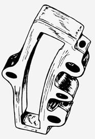
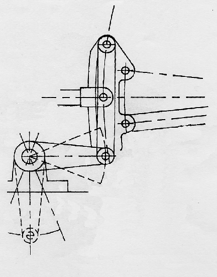
Almost coincident with the gear’s inception was the practice of offsetting the central suspension in order to correct angularities of both main crank and eccentrics, though this process appears to have been ill-understood and ignored by many designers. Today there can be no excuse for not designing a gear with the finest of attributes. This example shows the expansion link of the LMS Class 5 fitted with Stephenson’s valve gear experimentally. Click for a larger picture to view the offset trunnion.
Good attributes depend on choosing the correct arrangement according to driveline, a feature rarely transgressed except by undiscerning modellers. American practice was to employ launch-type links and to drive through a 180o rocker to slide valves on top of outside cylinders: British inside cylinders with collinear slide valves demanded the use of locomotive links and hence direct drive from larger eccentrics. Straying from the correct driveline reverses the match of angularities to produce inferior valve events and is difficult to remedy.
Because Stephenson’s gear can achieve near perfection in enabling a one-piece valve to supply both ends of a double-acting cylinder equally its design in any one particular case ought to follow a complete and correct procedure, in the knowledge that straying from its basic simplicity will impair its excellence. The primary tenet must be to achieve geometric symmetry, since any discrepancy will result in inequality of the valve events, either in forward gear or backgear, or in both. The gear comprises a straightforward eccentric drive for forward gear and another for reverse and should be kept so, including its suspension.
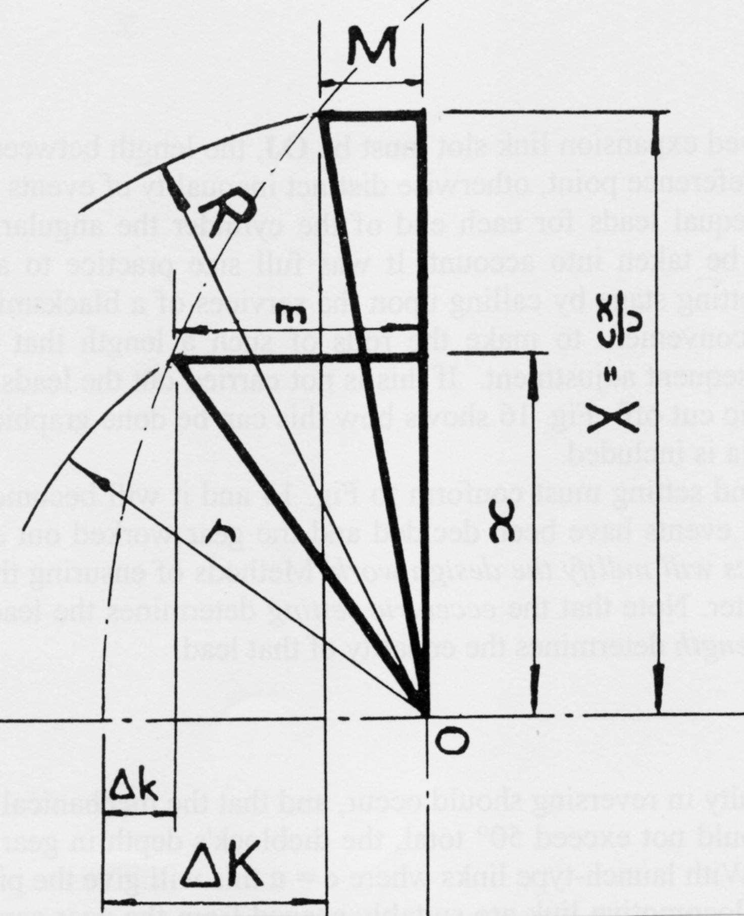
It is possible to proportion the parts so that the basic design does not transgress this principle once the required lap and lead are determined. The following example is for a launch link design for inside admission valves, relating the essential parts to an eccentric radius = 1.
Detailed design features:
Initial design work can be achieved very quickly using a spreadsheet such as that found on the DOWNLOADS page, enabling simple juggling of the lap/lead to address port requirements. Long travels are better accommodated by rocker arm enhancement in the manner of GWR locomotives and this keeps the eccentric throws at manageable dimensions. In this case entries into a spreadsheet should take into account the final enhancement ratio.
Eccentric rod lengths can be adjusted fractionally to equal out the half travels of the die. This is automatically incorporated into the spreadsheet, as is also the pin centre distance to prevent too much angular swing of the expansion link. Since it was common practice (lamentably) to alter the eccentric rod lengths in order to set the valves, the corrected length was not used in full size practice, yet always applied in Walschaerts’ gear. Valves should be set on their spindles by provided adjustment, otherwise the integrity of the gear itself is violated. Perhaps this was accepted as a practical compromise dating from the earliest times and never sensibly reviewed.
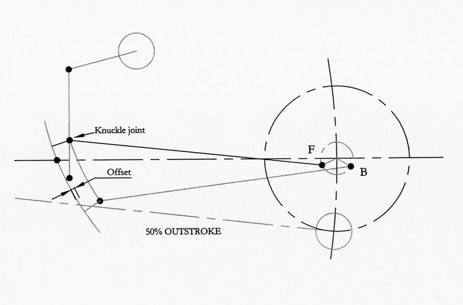
Expansion links should not swing more than 25 degrees for mechanical exigency. This limit is embedded into the spreadsheet and subsequent calculations conclude the exact amount of trunnion offset to counter inherent errors. It should be understood that this is carried out for 50% stroke and 50% cut off, the position of worst error, and therefore does not absolve the designer from good sense in providing proportions to gain the finest of distribution throughout the whole working range – if the design is good this procedure will enable excellence in events; if not it will merely make the best of a bad job. Improper suspension will counter any good initial design. Where convenient, placing the weighshaft ahead of the link can be advantageous, as revealed by the excellent equality to be found on the old LNWR Coal tank 0-6-0s.
The employment of locomotive links involves larger eccentrics because the die never approaches the line of the eccentric rod pins, usually by a factor of almost 2. The throw and settings are completely different from a launch link case and my design spreadsheet will accommodate this automatically to conform to the equivalent eccentric. Many model designs mistakenly substitute launch links for locomotive links without due reference to the correct driveline simply in order to keep eccentric sizes down. Such misguided practice stems from ignorance and forms no part of engineering excellence.
In the interests of standardisation the GWR used essentially the same valve gear to accommodate valve travels between 6″ and 7.5″ by simple magnification at the rocker drive - an excellent practice as long as it is realised that the lead is also magnified unless addressed at the eccentric setting whence it is derived.
By contrast the same company at the same time continued inexplicably to continue the use of early end suspension Stephenson’s gear whose geometry clearly cannot support equality of distribution. The lifting arm needs to be set oddly out of square in order to bias forward gear events at the expense of backward running. This archaic system is inherently incapable of producing good steam distribution and should never have been used, in spite of its almost universal application in traction engines. Its common appearance in the marine environment, where many miles may pass at a single expansion setting, is perhaps more excusable. Furthermore, nature has it that in a large vertically disposed engine the conditions for the upstroke differ from those on the downstroke.
Because Stephenson’s gear in its earliest form is capable through rational design of the very finest of equality in steam distribution there exist no reasons for the many patents purporting to improve it and no excuse for any poor arrangement. It is difficult to understand why so many poor examples were perpetrated.
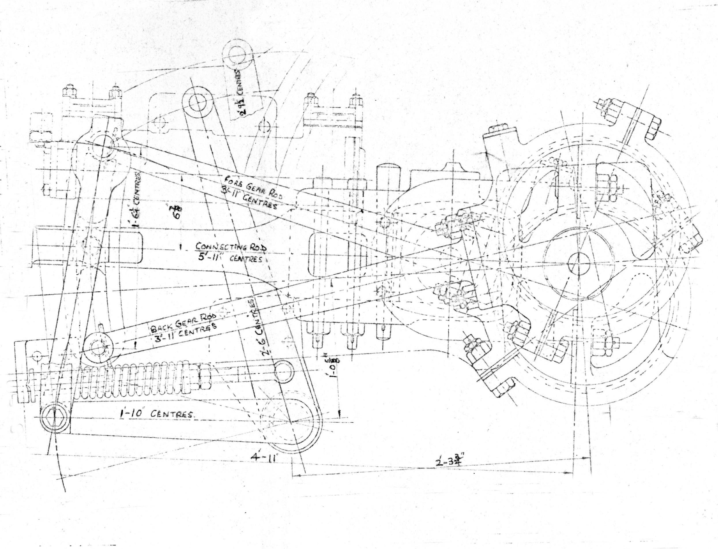
 Traction engines are the greatest abusers of the principles of good suspension and the use of the correct link for the driveline. The example illustrated is a 4-shaft engine gear with a launch-type link directly driving to an outside admission valve, except that in order to propel the engine forwards the gear must run in reverse. This would raise the linkage for most running, considered undesirable in the event of a sudden breakage in the suspension, and so the eccentric rods are crossed so that the motion is lowered into back gear.
The launch link enables smaller eccentrics in the restricted space but will require means of opposing the inherent angularity problems.
The illustration shows wrong thinking on two scores. Firstly, the square symmetry of the reversing arrangement cannot accommodate angularity errors at all, least of all those induced by the wrong choice of expansion link. The length of the lifting arm, length and angular setting of the lifting link and the position of the weighshaft are critical to steam distribution and will still require back gear events to be compromised in favour of forward running. (See the previous illustration)
Additionally, the designer has set the crank on back dead centre, at which point the advancing of the eccentrics pushes forwards all the mechanism by the amount of lap + lead in order that the rear port should begin to open. Therefore the lifting link is highly unlikely to be vertical, though few traction engine designers seemed to realise this!
Watching the movement in a simulator will show that generally a longer lifting arm, or a compensating shift in the position of the weighshaft, induces the asymmetry required to offset the poor equality, exactly on the same principles of the offset rocker of the GWR King locomotives or of those governing unequal expansion link swings in Walschaerts’ gear. In the absence of other means of countering the effects of angularity it has to be accepted that perfection is unavailable and that back gear may suffer somewhat in order to satisfy forward running.
It is worthwhile tracing the extremities of pin travel for both forward and reverse gears on paper, joining and bisecting these full gear positions, and thereby seeking a common position for the lifting arm eye. Resort to the simulator may then suggest minor diversion to suit the running range.
In retrospect it seems odd that traction engine designers sought to follow railway practices by using similar gears when their space limitations may well have suited the development of an entirely different valve gear, yet they so frequently transgressed simple principles that governed the railway designers. The heavy traction engine flywheel is intended to smooth out the uneven torque of the single cylinder and ought not also to be encumbered with greatly unequal power production between one end and the other.
Summary of design procedure:
First choose the correct link and driveline. Use the design spreadsheet to enter the parameters necessary for the cylinder requirements. Assess the increasing lead amounts and juggle the initial lead, lap and port opening to arrive at suitable full gear cut off and lead characteristics. If a final multiplying rocker ratio is contemplated these inputs must reflect that ratio.
If the arrangement is to be end suspended the spreadsheet use has finished and the simulator, with a simultaneous CAD drawing, is the best way forward to design the reversing gear. Somewhat perversely, symmetry of the lifting arrangements will not supply good event equality. The placement of the weighshaft and the lengths of the lifting components will alone determine the best events. Always put the weighshaft on the side away from the forward eccentric pin to bias fore gear. The joint between the lifting arm and link will be well forward of the expansion link in order to achieve any semblance of equality. Note that launch links should never be end suspended on locomotives and as rarely as possible in marine practice.
Sheet 2 needs inputs detailed in the downloadable supplement file. Once used, the Solver technique readily calculates all the gear trigonometry and the trunnion offset is the outcome. These calculations merely appear on the sheet so that the user may see when cells contain either # marks or minus signs, which must be absent before Solver is invoked. The suspension positioning is also determined.
The ‘Data’ sheet then has much of the simulator input material ready to transfer. The amount of adjustment necessary to produce the finest of results should be very little, once the valve has been set. The eccentric advance angle is critical to the lead function and correct valve setting is also crucial, but since the two harmonic elements are already fixed in the eccentric setting there can be none of the distortions found in Walschaerts’ gear. Any apparent problem is likely to be of the following:
A proportion problem: a mistaken input: a suspension item misplaced.
To use the simulator to analyse an existing design run a CAD drawing simultaneously. This is not only a check against input errors but also those elements out of proportion, particularly in the suspension. The most practical position for drawing is at dead centre.
EXAMPLES OF NEAR-PERFECTION
In spite of the standardisation of parts the GWR achievements with Stephenson’s gear in their Churchward locomotives cannot be surpassed and shows how the almost perfect event equality can be produced even with longer valve travels. There are many designs which irrespective of age reveal a similar degree of design knowledge and execution. Two examples with differing drivelines provide ample proof
QUEENLAND RAILWAYS Class PB15
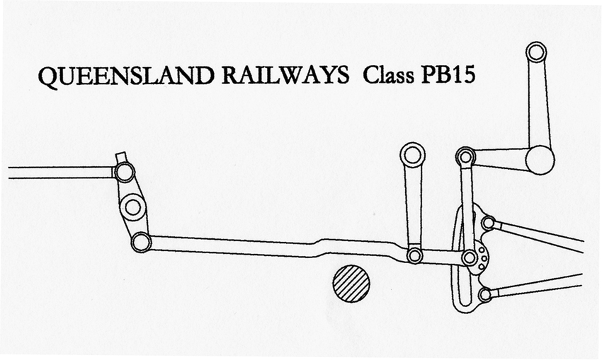 The first dates from 1899, when the Queensland Railways’ Ipswich Works designed the PB15 4-6-0s with direct drive to outside admission slide valves in typical American fashion. The expansion links were somewhat hybrid, with pins offset in launch link fashion but too widely spaced to allow die alignment in full gear. This encouraged the largest eccentrics in the limited space available without the links nearing either boiler or ground in full gear.
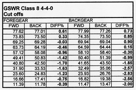
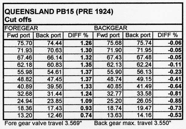 The suspension of the link is immaculate: centered and correctly offset and employing hangers on the valve connection. All the proportions and details display a sound knowledge of Stephenson’s gear and the resultant steam distribution table bears this out.
MANSON’S Class 8

The GSWR were fortunate in their design team: the Manson Class 4-4-0s used launch-type links to drive outside admission valves on top of the cylinder bores indirectly through a rocker of 180°.Again, attention to symmetry and knowledge of the correct suspension was responsible for first class distribution.
Later in life the rocker was eliminated by a successor with disastrous results not comprehended by the CME. Whither had the basic design skills disappeared?