 Although a brief glance into history (except on the Continent) might place Stephenson’s gear as being largely replaced by Walschaerts’ gear around the turn of the 20th century, both gears were invented almost simultaneously. In 1844 Egide Walschaerts invented a valve gear that by 1848 appeared very much as it does today. The primary reason for a more universal adoption of Walschaerts’ gear was its general suitability for mounting outside the frames, convenient for maintenance and permitting more strongly braced frames.
All gears have to provide the combination of two harmonic motions and in the case of Walschaerts’ these are from the main crosshead and the return crank. Unfortunately this often gives rise to the misconception that they can be treated separately in order to understand their functions. That the student should resist this temptation will soon become apparent; the alteration of a single part necessarily alters the whole. To take the point further, far too many ignore the suspension of the gear, ie. the weighshaft and lifting arm and combination lever support where used, as being essential to correct functioning of the gear.
On modern large-wheeled engines little latitude for ideal placement may be available for a shaft which of necessity passes through the frames and beyond. The inside gear of the GWR 4-cylinder 4-6-0s avoided this constriction to advantage.
In designing the initial parameters it is perhaps wise to realise that at the time of its invention valve travels were short, with slide valves necessary for outside admission. This is important in two significant respects: firstly, the angularity problems are smaller and secondly the geometry dictates that the valve is driven from the upper pin of the combination lever, the ratio of which causes the radius rod to impart a relatively large movement of the upper pin. The effect on reversing these pins for inside admission valves is to impart a slightly reducing ratio, necessitating a much greater influence from the radius rod and hence the return crank throw, with a consequent increase in expansion link swings of around 20%. Long travel valves exacerbate the problems, none of which could be conjectured at the time of the invention. Compaction of the gear in short wheelbase examples gives rise to similar difficulties in obtaining good event equality; where reverse running is expected to be used as frequently as in a forward direction the facility to bias forward running at the expense of reverse is forfeit.
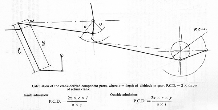
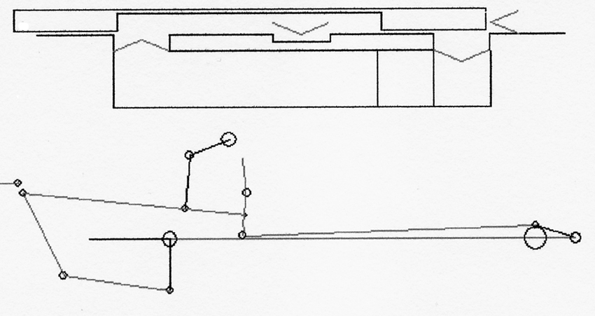
A sensible initial design may be had from the basic geometry shown in the diagram and the spreadsheet on the DOWNLOADS page quickly lays down the structure for both inside and outside admission simultaneously. The spreadsheet cannot analyse other than equiangular expansion link swings, which mammoth mathematical exercise is best left to final adjustments in a simulator. Be aware of the much greater angles of swing required for inside admission cases.
Detailed design features:
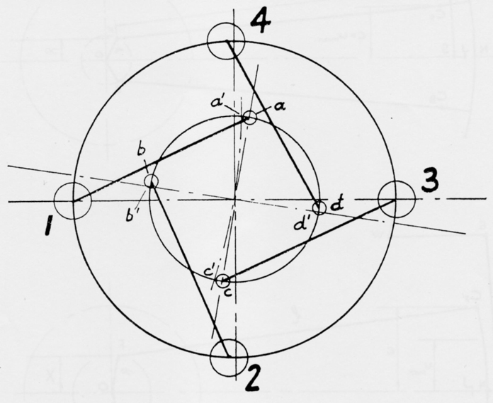
Tracing each item in the chain provides an overview of their functions and specific problems that can influence their design. The first common principle, though not inviolate, is that at either dead centre position of the crank the return crank and eccentric rod pair render the reverser unable to impart any motion to the valve throughout its full working range. This then sets the leads exactly equal once the valve is also set so. The leads cannot be set equal without this condition – attempts to set the valve to equal leads where the gear cannot support them simply destroys the equality of other events. Notice particularly that the lead function normally associated with the crosshead and combination lever can be readily influenced by the parts of the 90o component – it is unwise to think of the two harmonic motions as separate entities.
Lead is such a very small amount within a large mechanism that it behoves the designer and builder to observe critical accuracy. A small discrepancy in the equality may be acceptable or even undetectable except by simulation, but working bearing clearances and subsequent wear could easily remove the desired lead altogether. More information is given on the LEAD page.
The actual angular setting for the return crank and eccentric rod will now depend on the expansion link position and its tailpin. The expansion link must sit square to the radius rod in mid gear and the so-called backset of the tailpin theoretically lessens as the inclination of the eccentric rod increases, and in many inside gear arrangements where the eccentric diameter might be excessive the pin may be well up towards the expansion link trunnions and cause the backset to become positive. All this is largely relative to the production of equiangular swings, which may or may not be best for a particular design.

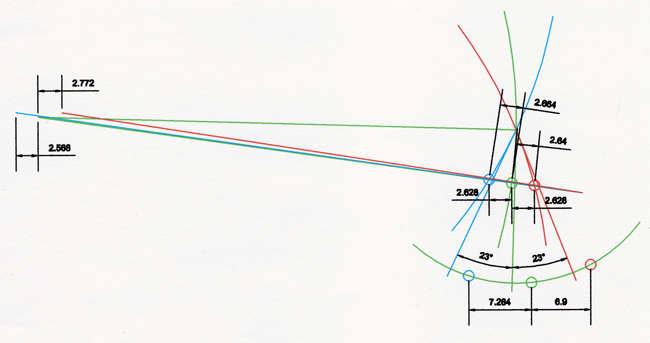
Of itself, equal angles of expansion link swing cannot deliver equal movements of the valve. The illustration shows in detail an arrangement where equal swings are deliberate, and the resulting distances at the radius rod front pin reveal the linear discrepancies. This is not the whole story, of course, as the designer must be aware of all the accelerations and decelerations throughout a full cycle; the emphasis in design must be on timing values and not necessarily on distances.
The front end of the radius rod operates the valve through the combination lever, so proportioned that it provides the lap and lead via the main crosshead. Precisely as its name suggests, the combination lever combines the two essential components of the valve gear and in doing so takes its orders from both functions simultaneously – one cannot move without influence from the other.
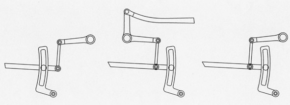
It should be apparent at this stage that the reverser’s means of supporting the radius rod greatly influences the choices, some of which are illustrated. The swings of a hanger or the constraints of a die must be arranged to balance as a whole so that the valve operates as desired, and may demand expansion link swings disparate by 2o or more. The variables are legion and best resolved by computer simulation, where the results are assessed quickly.
It will be found in most cases that given equal depths in gear for forward and reverse working the percentage of cut offs in back gear will exceed those in forward gear by as much as 6%. Although some engineers did not favour using the upper expansion link half for forward running because the drive is then indirect, the position is in fact little different from the many cases of rocker use in valve gears, though the results are not at 180 degrees. In the average inside admission arrangement there is therefore scope for reducing the pitch circle using a shorter leading return crank, such that an adequate foregear starting cut off is maintained. Holcroft was evidently aware of this and promoted it on the Southern Railway, choosing a rather cramped arrangement which did it no special favours. The larger BR Standard Classes, though not employing the upper half for forward running, gave more space to the hanger arrangement but failed to optimise the geometry.
Even the apparently symmetrical LNER/LMS extended radius rod reverser with an equiangular lifting arm shows this trend. The same valve travel in reverse gear does not necessarily produce the same cut offs as it achieves in forward gear simply because the valve excursions are measured against a reversal of the piston’s relative excursions. This is why tables of events list different figures for midgear at the minimum of the forward tabulation than those for reverse. To add to this, the working of the die in the upper half of a curved ‘rocker’ (expansion link) is quite different in detail.
Those examples of hanger suspension, whether in front of or behind the trunnion, introduce other complexities and require very careful placement to obtain good working in both forward and reverse. Many designs tend to favour forward gear where more astute design work could have produced a better compromise. The best examples use the suspending element to counter other inherent timing errors and this minimises die slip and wear.
Longer valve travels inevitably make this area more difficult to appease. The worldwide use of a hanger for the rear end of the radius rod was extensive, generally raising the number of badly orientated ones, and simulation with experience seems the only sensible way to go.
It is simplistic to regard the crosshead contribution as the similar triangles portrayed in most texts and it is possible to employ the anchor link to delay or advance this component relative to that from the expansion link in order to equate the events of one port with those of the other.
It is mechanically necessary to provide in the anchor or union link a flexible connection. Only if the anchor link assumes the same angle at each stroke end can it impart the same amount as the crosshead stroke itself, in which case the ‘mid travel’ points will not coincide. If the ‘mid’ points coincide the angular extents will differ. This therefore places the anchor link at the forefront of Walschaerts’ critical adjustment areas, greatly influencing the shape of the curves presented in the simulator. In fact what is happening is the balancing of one component’s distortions against those of the other component. As the usual combination lever ratio of pins is around 9:1 the anchor link provides an excellent and sensitive point of adjustment. By comparison the backset is much less sensitive, though useful for this purpose. Bear in mind that these areas of adjustment refer to the design stage.
The combination lever and radius rod require support either by a valve crosshead guide or by a hanger. This latter was more frequently a feature of Continental practice and has the admirable propensity, with a double arm, of providing the means of increasing valve travel without incurring objectionably large pitch circles and the angularity problems stemming therefrom. Remember that Walschaerts knew nothing about long travels and inside admission valves at the time of invention: some modern designs struggle to emulate the best of those dating from early in the 20th century.
There are small inherent timing errors at the return crank, which is normally set at the dead centres such that the tailpin of the expansion link assumes the same position in both cases. That automatically means that a variable error exists at all other points by the transmission of rotary to linear motion. The error increases with pitch circle diameter increase, calling for the least that will provide sufficient travel to the valve. Greater pitch circles and expansion link swings are demanded by the use of inside admission and designers of more modern locomotives require skill and ingenuity to avoid poor steam distribution. Symmetrical layouts for short travel outside admission valves reduce the problems dramatically irrespective of scale. The correct angular setting for the return crank has the pins at 90o to a line passing from the tailpin to the axle centre. It may be noted that the return crank pin is the only one in the gear that revolves through 360o, hence the common use of a roller bearing, which is inappropriate for all the other pins.

It is not difficult to conclude that the detailed design of Walschaerts’ gear is more complex than that of Stephenson’s gear, which has the advantage of combining the two components directly at the eccentric setting and merely requires that nothing in the subsequent chain of the mechanism should disturb its propensities. Mechanically, its greatest disadvantage is that of having to lift the whole mechanism in order to reverse the motion or to achieve intermediate expansion working. Walschaerts’ gear readily satisfies this condition since only the raising of the radius rod is involved.
Summary of the design procedure:
From the cylinder and port requirements feed the cells marked ‘enter’ in the spreadsheet and adjust lap, lead and port opening to obtain a suitable full gear cut off. All else is calculated automatically and the results shown for both inside and outside admission, including the 4 possible return crank lengths. The calculations at this stage assume equiangular swings of the expansion link.
Proceed to the simulator, using the parameters generated in the ‘Data’ sheet. Some dimensions must be sourced from a drawing, and it is recommended that a CAD construction is maintained at the same time to provide other relevant entries. Where pure analysis of an existing gear is contemplated a CAD construction will prove invaluable in discovering those items either missing from a drawing or found to be incorrect. The drawing should be constructed with the main crank on back dead centre.
The simulator results quickly reveal the levels of equality between both ports. The backset is a suitable modifier and will be found to be fairly insensitive, but the anchor link quickly alters the shape of the cut off curve as opposed to its position. Reset valves at each modification to ensure that the desired effect has taken place. Modifications to the suspension elements may need some little trial and error, the skills of which will develop with use - the simulator will only show the results of the user input and cannot supply design.
Examples by analysis:
It is not often that a motion drawing adequately and distinctly provides all the information necessary in order to reconstruct the gear in CAD, but Thompson’s LNER B1 4-6-0 is one such. Symmetry abounds. The return crank angle depends on the pitch circle and the distance and height of the expansion link tailpin relative to the axle at dead centres. It is a simple piece of geometry often ill-devised for no apparent reason and the gear’s ability to support equal leads, the smallest quantity in a large piece of machinery, is highly dependent upon this principle. In practice the eccentric rod length is adjusted to maintain the principle even though veracity assumes that the return crank and its angular setting, together with the drive from the crosshead, are correct.
In this case the angle, length of return crank and eccentric rod length conform precisely and confirm the somewhat obscured pitch circle radius dimension. There is an apparent assumption that at dead centres the union link is parallel with the gear line which is proven in the reconstruction, though another that purports the radius rod top pin, expansion link trunnion and weighshaft all to be in line proves not quite so. The radius rod slopes at 0.1 degrees!
Backset of the tailpin is clearly zero and we can expect that the expansion link swings are unequal, in fact by 2.11 degrees. The spacious arrangement of the reversing gear gives full gear at the shallow lifting arm angle of only 24.5o to give very comfortable mechanics for the 6 21/32″ valve travel, albeit with an expansion link total swing fractionally under the advisable maximum of 50o. The standard LNER reverser supports the radius rod extension by means of a slot and die allowing no adjustment to accommodate die slip but does not receive possible errors from a poor hanger arrangement. The unequal expansion link swings have therefore been deemed to offset the fixed dieblock excursions rather well in combination with a long anchor link.
Simulation verifies the faith placed on introduction to the drawing. Frequently one has to set the valve carefully in order to maximise events, but this case required no setting whatsoever to realise an excellent fore gear pattern with adequacy in back gear. The theoretical full valve travel of 6.716″ compares very favourably with the 6.562″ recorded in the official table of events. Only the 1/8th″ lead is somewhat optimistic.
The events will never tie in exactly with results obtained by actual measurement, as the simulation contains exact dimensions without manufacturing tolerances, bearing clearances, etc. The pattern of events produced by the gear, particularly the differences column, should reflect those obtained by either the large gear model of the drawing office or those taken manually from a completed engine. Also bear in mind that the simulator has no means of massaging figures!
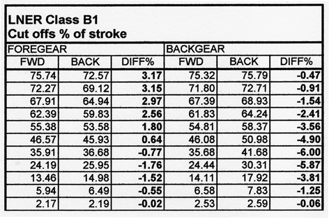
Thompson’s B1 does exactly what it says on the box, so to speak, and the irregularities of back gear mirror faithfully once the full gear parameters are set to the nominal figures on the drawing. The B1 gear benefits from occupying a large symmetrical envelope and the parts contain dimensions never finer than 1/32nd″, and even these prove by CAD to be precise. Could it have been better?
Undoubtedly computer simulation could have improved the events numerically, but the skills of the LNER team have produced a good gear whose performance in practice might gain little from high-tech tinkering. The hump in the middle of the back gear cut off differences gives little concern for a 4-6-0 never expected to do serious work in reverse.
Enthusiasts, apart from partisanship, might be tempted to compare the LNER mixed traffic engine with the LMS Black Five and the GWR Hall. 26,880, 25,455, and 27,275 lbs respectively are the recorded tractive efforts - all comfortably close in the mixed traffic area.
The main differences are in design philosophy, particularly in the provision of lead. Whilst the B1 barely manages a constant 1/8th″ the Hall is 1/8th″ negative in full gear and does not reach 1/8th″ positive until the middle of its cut off working range. The Class 5 reflects LMS general practice at ¼″ but is stated as being divided slightly unequally between the ports, though it is not specified whether this setting is hot or cold. (A Standard BR Class five is very similar in most respects to the LMS version excepting the valve gear itself, which is geometrically inferior to that of the older engine.)
Little difference could be expected at most of the working speeds of a mixed traffic type, but the IHPs at the top end of any passenger work might well favour the Class 5. There are, of course, many other design features that might influence a comparison. All three contestants proved worthy of building in large numbers.
Darjeeling Class ‘B’
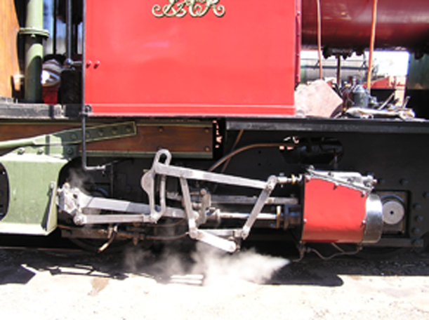
 Old and delightfully quirky though they appear, these locomotives provide a shining example of early excellence in Walschaerts’ gear design. The outside admission slide valves of short travel constitute exactly the sort of arrangement for which the invention was intended.
The envelope of the gear is a squat rectangle containing a long anchor link, small pitch circle and minimal expansion link swings and one might expect little problem in attaining good event equality. The zero backset in the LNER B1 could hardly ‘work out’ to that figure – it is obviously implanted deliberately. In the case of the ‘B’ Class the tailpin is placed exactly on the expansion link’s central curve – also deliberately so and producing unequal swings as a direct result. This is deceptive, as the angular discrepancy is a mere 1.38o due to the short travel and squat envelope.
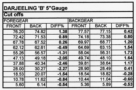
The events, however, prove by simulation to be magnificent, addressed to the heavy gradients expected without much compromise in reverse. It is tempting to accord this excellence to the small pitch circle and short valve travel but due praise of the design details should be recorded. The rather spindly rods are more than capable of taking the light loads involved.
The GWR 1500 tank and its 5″G Model ‘SPEEDY’
An example of the difficulties attending compaction of the envelope is to be found in the GWR 1500 Class 0-6-0 engines of which only 10 were made. Compared with the exceptionally good King Class valve gear this little tank design gave the design team a headache, compounded by the adoption of an anchor link driving directly from the crosshead little end pin. This feature immediately contracted the combination lever to give pins so close to each other at the top end to warrant especially small pins and render it necessary to crank the front end of the radius rod for adequate clearances.
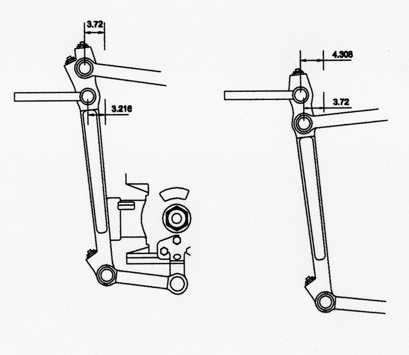
This feature was ignored by LBSC in his design for Speedy, a drop link being provided, and there are other quite small divergences which plunge the model design into trouble. Not only does this impose mediocre performance but the shortness of full gear cut off often leads to poor starting. Numerous and misguided have been the modellers’ attempts to rectify the situation, since the proponents little understood the problems of compaction. It is interesting to superimpose the model design over the Swindon drawing at the same scale (but without equating the valve and ports). Excepting the drop link the gears appear closely matched and shows just how so very near a design can produce hopelessly different results.
In the end Swindon managed a very creditable performance under the circumstances. Much of the compaction arises from the proximity of the cylinder to the driving axle and use of the trailing axle to originate the drive (like the USA Dock Tanks) would have created a better envelope. Most locomotives employing a leading bogie benefit from greater space in which to design the gear – all other six-wheeled engines of short wheelbase may suffer from compaction.
LBSC did not appreciate the problems. Typical of the design of small scale engines, the use on moving empty stock in and out of Paddington station of a 1500 is ignored in the duties expected of a smaller version, which equate more nearly to an express passenger locomotive. Modellers rarely potter about on shunting duties and should design as befits the new role. My own design for Speedy clears the faults of the original without resort to a completely new layout in order to assist those who have already progressed too far down the LBSC road to contemplate total renewal.
BR CLASS 7
The BR Class 7 motion owes much to American layout practice with equiangular expansion link swings and a radius rod hanger forward of the trunnion. In retrospect this proves a doubtful way to deal with long valve travels and the events are generally inferior to those produced 20 years earlier. It is of interest to investigate the points of relative sensitivity.
First the angular swings themselves. In right hand elevation the backset produces an anticlockwise angle of 24.43o and a clockwise one of 24.33o – essentially equal. In full forward gear this accounts for 78.37% cut off (front) and 74% (rear) and a port opening disparity of almost 7/32″. Port opening as a distance, rather than time, is relatively unimportant, though it is interesting to see what it takes to remove this disparity and to reveal the relative insensitivity of backset angle. The backset has to be reduced by half in order to equate port openings, yet the cut offs remain similar at 78.14% and 72.54%. On the other hand, cut offs of 78.92% and 75.53% from a backset angular increase of some 5.5o are little different in equality from standard, giving the same port opening inequality from angular swings of 24.6o and 26.23o. Quite clearly the backset is shown to be relatively insensitive to adjustment, as expected. [It ought to be pointed out that the lengths of the eccentric rod and return crank have been recalculated to maintain lead equality at each alteration.]
More surprising in this particular case is the resistance of the anchor link to affect results. Even 1″ either side of the 13.8″ given length has but little influence and leaves the hanger arrangement fully in charge of the difficulties. Moving the point of suspension (1″) on the radius rod quickly disturbs the port openings, the cut offs much less so, whereas shifting the weighshaft 1″ horizontally either side equalises port openings at the expense of cut off disparity.
The real culprit is the enlargement of a design which could adequately cope with shorter travel valves, say up to 6″, but becomes a victim of larger angularities above that. Pitch circle radiuses of 7″ or more compare ill with a Stephenson’s eccentric equivalent of only half of this. The design becomes an exercise in deciding at what running cut off it is best to equalise events without too much sacrifice elsewhere. And the less said about back gear the better!
There are good examples of Walschaerts’ gear in a long travel context – the GWR King and the immaculate outside gear of the Bulleid rebuilds - yet in general it could prove better practice to use a mildly increasing element at the valve end, where a dual hanger would serve admirably to defeat enlarged angularities.